PRODUCTS


1. Product introduction
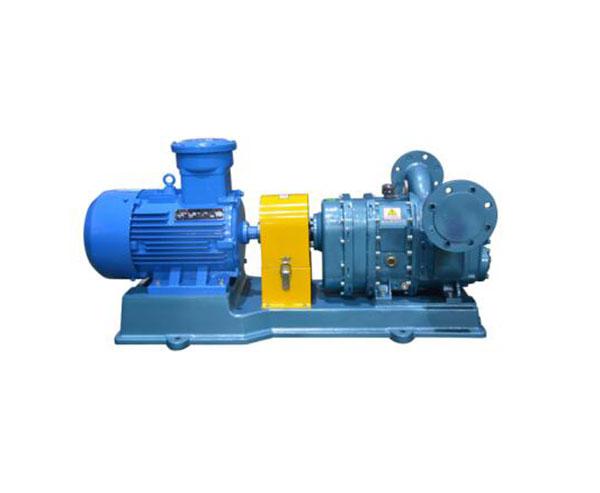
YZB series rotary cam rotor pump is a self-priming piston rotor pump, which is a new product designed, tested, researched and developed by our company by absorbing relevant advanced foreign technologies. On the basis of the successful design of the cam rotor pump abroad, further optimization tests were carried out on the geometric shape of the cam profile of the rotor and composite materials, and a series of technological breakthroughs were made by adopting advanced processing methods, realizing the excellent characteristics of multi-purpose and high efficiency of the product. The structure is small, the volume efficiency is high, the operation is stable, the vibration is small, the noise is low, and the liquid flow path through the pump cavity is short, The shear force on the medium is very small, which is especially suitable for conveying paste like medium containing solid particles, especially for viscous multiphase mixture with high viscosity, strong abrasiveness and sensitive to pulsation.
The flow of YZB self-priming piston rotor pump is proportional to the speed. Each pump type adopts built-in gear reducer and synchronous transmission mechanism. Under the pressure load required, the set speed and power can be configured to stabilize the output flow, which is especially suitable for industrial liquid delivery on the process production line.
2. Product pictures
3. Scope of application
1. Environmental protection and treatment: sewage, municipal or industrial sewage treatment plant sludge, thickened sludge, dosing pump, dehydrator feeding, flue gas desulfurization lime slurry, fertilizer solution, water oil mixture and industrial waste mixture discharge.
2. Fire fighting: conveying fire water, foam slurry, etc.
3. Petrochemical industry: transportation of sludge, heavy oil, heavy oil, asphalt, coal water slurry, chemical fiber slurry, gasoline, diesel, kerosene, aviation kerosene, lubricating oil, various catalysts and various solid liquid gas multiphase mixed liquid slurry.
4. Daily chemical industry: convey various alcohols, lipids, glycerin, facial cleanser, shampoo, shower gel, skin cream, toothpaste, soap liquid, detergent slurry, etc.
5. Building materials and mining: convey mine sludge, cement slurry, drilling waste liquid, lime slurry, gypsum slurry, etc., and various flotation slurry and tailings slurry before concentration.
6. Ships: transport sewage and leakage liquid from ships.
7. Agriculture: transportation of liquid fertilizer, animal food, waste food, biogas digester, etc.
8. Fine chemical industry: transportation of dyes, pigments, various intermediate sizes, chemical auxiliaries, printing and dyeing auxiliaries, silicone oil, adhesives, coatings, and various colloids and suspensions.
9. Medicine and food industry: conveying ointment, pill paste, lotion, fruit puree, crushed vegetables and fruits, chocolate, syrup, honey, jam, condensed milk, dairy products, yeast slurry, meat slurry, distiller's grains, and various fermentation and wet abrasive slurry. 10. Paper industry: conveying pulp, adhesive, paint, mineral powder filler pulp, etc.
11. Building materials and ceramics industry: conveying various glazes, mineral powder slurry, etc.
4. Product Features
1. The cam pair is conjugate engaged and has synchronous gear transmission. The cam engagement has no sliding wear and long service life.
2. Depending on the space volume between the rotor and the pump chamber, a fixed infusion displacement will be generated. When the outlet head changes, the volume efficiency of the pump will be very little affected. Therefore, as long as the bearing power and sealing capacity allow, the delivery flow will always remain stable.
3. It relies on the pumping principle of volume transfer, rather than relying on the liquid inertial moving head for infusion, and the rotor speed is low and the liquid flow head is small. Although the pump volume is small, large diameter pipes can be used for transportation, so not only the loss of pressure head along the way is small, but also the head is high, and the construction cost of the pipeline is greatly reduced.
4. Since the volumetric efficiency is not affected by the working pressure and the output flow is stable, the pumps running in parallel on the branch pipe network are basically in a linear superposition relationship, and the pump characteristics are basically not affected.
5. Since the output flow is proportional to the pump speed, independent of the pipeline characteristics, and can maintain a certain flow output even at very low speed, speed regulation can be adopted for controllable quantitative transmission, which can be applicable to the process oriented process transmission.
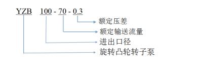
5. Model Meaning
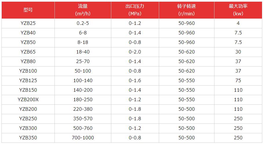
6. Specifications
7. Installation method
(1) The piston rotor pump shall be installed and fixed on a stable foundation. It is better to lay a cushion between the base and the foundation. Ensure that the pump will not affect the vibration of the pipeline when it is started. The pump is not affected by other mechanical vibration.
(2) When installing the pipeline, it shall be noted that the inlet and outlet pipelines of the pump shall not exert force on the pump and shall be equipped with corresponding supports.
(3) Sufficient maintenance space shall be reserved for the pump during installation to facilitate equipment maintenance in the later period.
(4) It is not recommended to lay convex pipes on the suction pipe to prevent air blockage.
8. Precautions
(1) YZB piston rotor pump is generally applicable to the delivery pressure below 1.2MPa. Because the volume efficiency of the pump is different under different working pressures, and its rated flow is also different, when selecting the pump type, the pump type with the required delivery flow should be selected according to the pressure head required by the delivery pipeline system. Generally, under constant working conditions, the pump type can be selected together according to the pipeline system design. When changing the working conditions, the pump type should be selected according to the heavy load working conditions, and the speed regulating motor can also be used to adjust the working conditions of the pump in real time. It can also be driven by internal combustion engine or other prime movers.
(2) Corrosive or polluting media shall be described during model selection, so as to determine the solution of rotor composite material and mechanical seal, and it shall be determined according to the technical agreement when necessary.
(3) YZB piston rotor pump is suitable for starting under liquid filled state and reaching rated flow in a short time. However, due to the limited suction head of the pump, when using straight reducing nozzle, liquid filled starting measures should be taken, and the simple method is to use imported check valve or 90 ° nozzle.
(4) The pump shall be started or operated at the rated opening of the outlet pipeline. It is forbidden to start when the pump is turned off to avoid overload. In order to avoid possible misoperation or hazardous working conditions, it is recommended to set safety relief valve bypass on the pipeline at the outlet and inlet sides of the pump.
9. Frequently Asked Questions
(1) If the piston rotor pump can not be started normally, it may be that solids settle in the pump body after it stops running for a long time.
(2) The pump can not self-priming, which may be caused by blockage or air leakage of the inlet pipeline.
(3) The medium flowing out of the middle isolation chamber may be the mechanical seal is damaged.
(4) The noise and vibration may be caused by the lack of liquid in the pump cavity, which causes cavitation.
10. Use needs
(1) When working, the increase of viscosity, flow and pressure will easily cause overload of the motor, so check whether the pressure gauge, safety valve and overcurrent protection device are normal.
(2) In order to avoid cavitation when the pump is started, the pump chamber shall be kept in the liquid filled state. If the pipeline system can avoid cavitation, a straight reducing pipe can be used, otherwise a 90 ° reducing pipe or at least one 90 ° pipe shall be used at the inlet side. When the liquid flow rate and pipeline pressure at the user end change frequently, it is recommended to set a bypass relief circuit between the inlet and outlet of the pump, and set the rated working pressure to ensure that the pump unit operates in a safe state.
(3) Fill or regularly replace the cleaning fluid (generally water or thin oil) to keep the mechanical seal clean and lubricated;
(4) When dealing with the faults related to the mechanical transmission part, the end cover and transmission box shall be disassembled from the front end of the transmission input. It is unnecessary to disassemble the pump body and the connection between the pump body and the gear box.
- DYB Portable Vane Pump
- HWQB Explosion proof Submersible Pump
- HW Adblue/Methanol Pump Series
- KCB Gear Oil Pump
- KYB Self-Priming Vane Pump Series
- LPG Liquefied Gas Pump
- WCB Portable Gear Pump
- Pipeline Pump Series
- Explosion-Proof Motor Series
- Diaphragm Pump Series
- Flowmeter Series
- Oil Drum Pump Series
- DC Pump Series
- Magnetic Pump Series
- Chemical Pump Series
- Centrifugal Pump Series
- Vacuum Pump Series
- Metering Pump Series
- Rotor Pump Series
- Multistage Pump Series
- Sanitary Pump Series
- Screw Pump Series
- Oil Gun And Small Flow Meter
- Explosion-proof type control cabinet
Scan the code to follow Facebook
Phone/wechat/whatsapp: 15868545868 18968868555
Email: haiwan@haiwanpump.cn
Http: www.haiwanpump.com
Add: Meiao Street, Qiaoxia Town, Yongjia County Wenzhou City, Zhejiang, China

Scan The Code To Contact Us