PRODUCTS
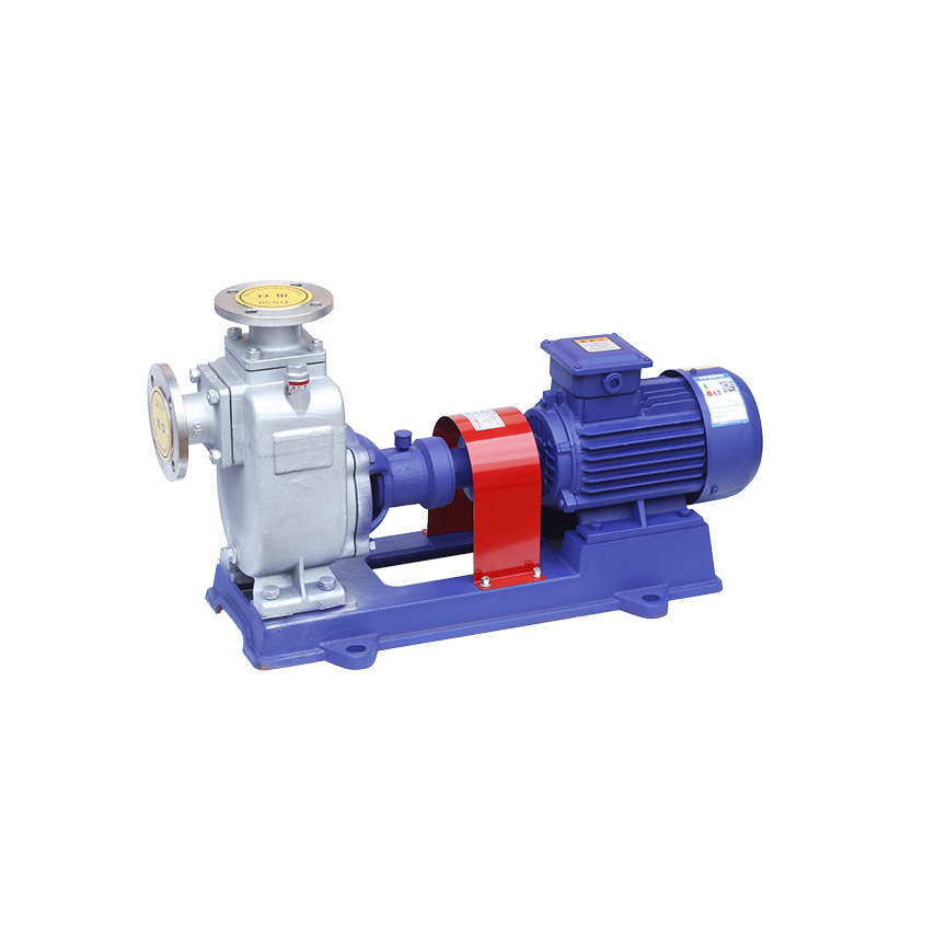


The ZX series self-priming pump produced by this unit is an energy-saving pump product developed after absorbing, digesting and improving the relevant technical data at home and abroad. The pump is a self-priming centrifugal pump, which has the advantages of compact structure, convenient operation, stable operation, easy maintenance, high efficiency, long life, and strong self-priming ability. There is no need to install a bottom valve in the pipeline, and it is only necessary to ensure that there is a quantitative lead in the pump body before working. Therefore, the pipeline system is simplified and the labor conditions are improved.
Pump application range
1. It is suitable for urban environmental protection, construction, fire protection, chemical industry, pharmaceuticals, dyes, printing and dyeing, alcohol making, electricity, electroplating, papermaking, industrial and mining washing, equipment cooling, etc.
2. Install the rocker-type sprinkler, and after the water is flushed into the air, it can be scattered into small raindrops for spraying. It is a good tool for farms, nurseries, orchards and tea gardens.
3. It is suitable for dry clean water, sea water, chemical medium liquid with acid and alkalinity, and slurry with general paste (medium viscosity <100 centipoise, and the solid content can reach below 30%).
4. It can be used with any type and specification of filter press, and it is the most ideal matching pump for pressure filtration when the slurry is sent to the filter press.
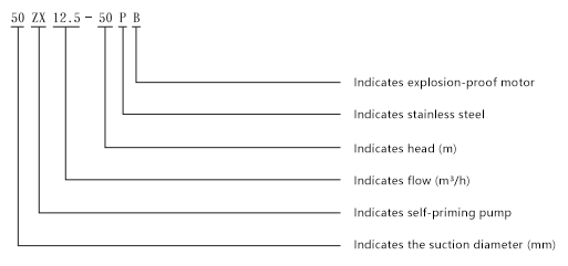
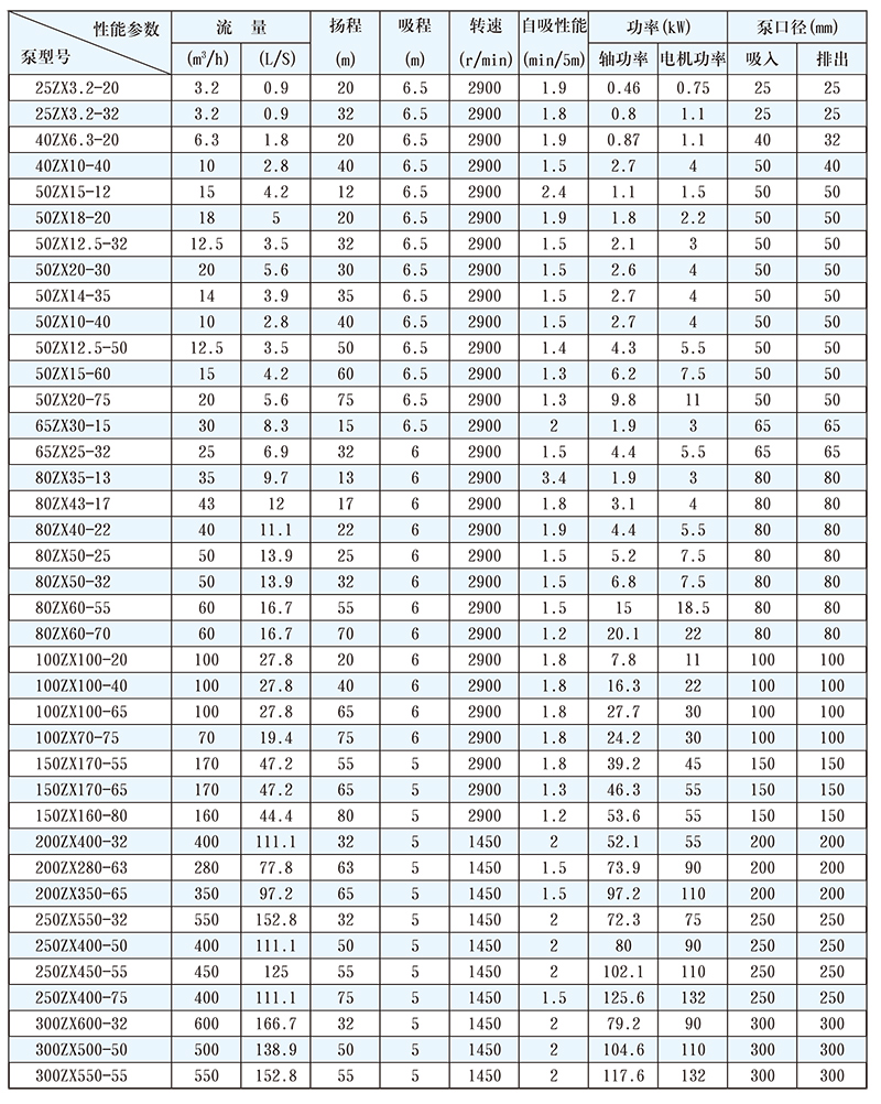
Pump model and performance parameters
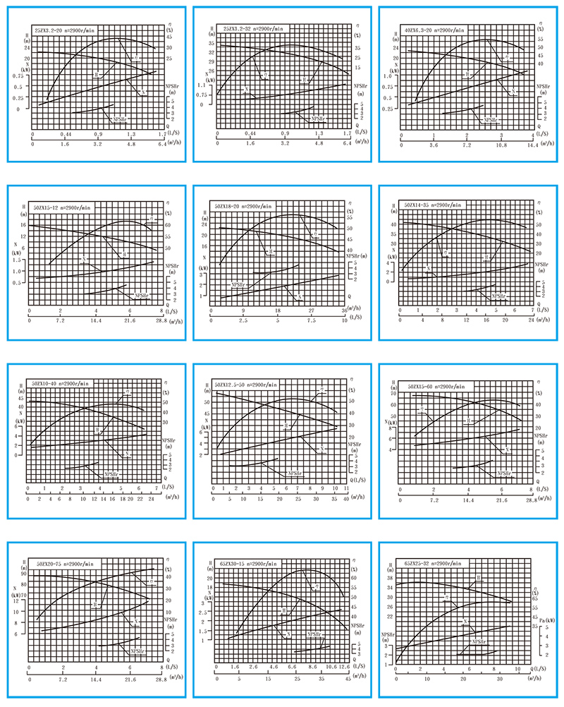
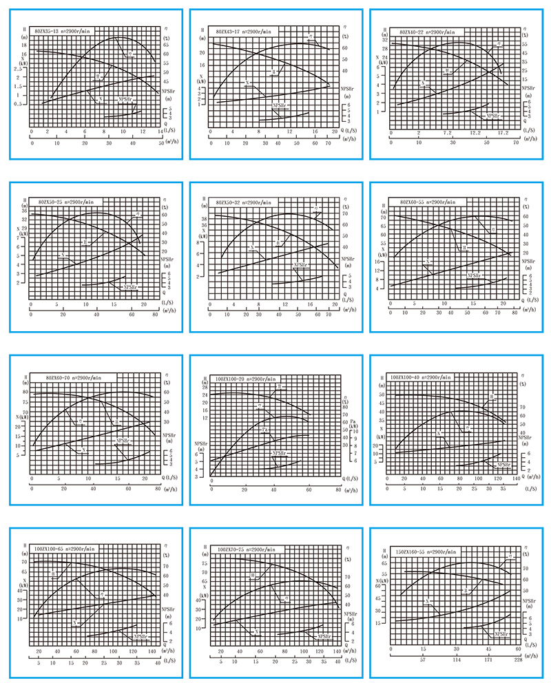
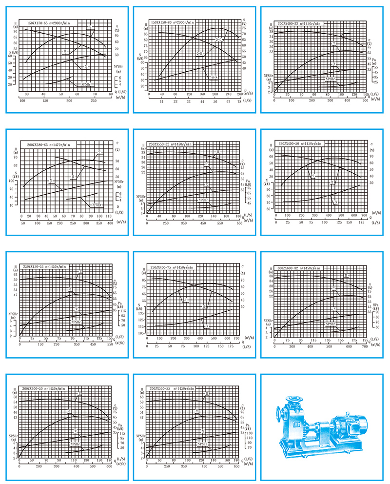
Performance Curve
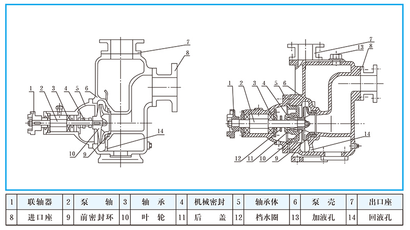
Working principle and structure description
The pump adopts the pump body structure of axial liquid return. The pump body is composed of a suction chamber, a liquid storage chamber, a scroll chamber, a liquid return hole, and a gas-liquid separation chamber. After the spring is started normally, the impeller sucks the liquid stored in the suction chamber and the air in the suction pipeline together, and is completely mixed in the impeller. Under the action of centrifugal force, the liquid entrains the gas to flow to the outer edge of the scroll chamber, and a white foam belt with a certain thickness and a high-speed rotating liquid ring are formed on the outer edge of the impeller. The gas-liquid mixture enters the gas-liquid separation chamber through the diffusion tube. At this time, due to the sudden decrease of the flow rate, the lighter gas is separated from the mixed gas-liquid, and the gas continues to rise and discharge through the pump body spout. The degassed liquid returns to the liquid storage chamber, and enters the impeller through the return hole again, where it is mixed with the gas sucked in from the suction pipeline inside the impeller, and flows to the outer edge of the impeller under the action of the high-speed rotating impeller. As this process goes on over and over again, the air in the suction line is continuously reduced until the gas is exhausted, the self-priming process is completed, and the pump is put into normal operation.
There is also a cooling chamber at the bottom of the bearing body of some pumps. When the bearing temperature rises over 70°C due to the heating of the bearing, the cooling liquid can be injected into the cooling chamber through any coolant pipe joint for circulating cooling. The sealing mechanism inside the pump to prevent the liquid from leaking from the high pressure area to the low pressure area is the front and rear seal rings, the front seal ring is installed on the pump body, and the rear seal ring is installed on the bearing body. When the efficiency and self-priming performance of the pump are reached, it should be replaced.
main structure name
pump installation
1. When the pump and the motor are directly connected to the drive, attention should be paid to the coaxiality of the pump shaft and the output of the motor: the accuracy of the pump installation has a great influence on the running stability and service life of the pump, so it must be installed carefully and carefully and correction.
2. The pump coupling must be fastened with a nut, and the nut should be tightened to prevent the nut from loosening, otherwise it will easily cause the impeller to move and cause mechanical failure.
3 In order to keep a certain amount of storage fluid in the pump body, in order to achieve better self-priming ability and prevent dry friction of the mechanical seal, the inlet of the pump must be higher than the center line of the pump shaft.
4. Attention should be paid to the installation of the suction pipe:
A. The installation height of the suction inlet should not exceed 5 meters. When conditions permit, the installation height of the suction inlet should be as low as possible below the lowest water storage level of the pool, and the length of the suction pipe should be shortened as much as possible, and fewer elbows should be installed, which is beneficial to Shorten the self-priming time and improve the self-priming function.
B. Valves, flanges, etc. in the suction pipeline should be strictly prevented from leaking air or liquid, that is, no air leakage is allowed in the suction pipeline.
C. Internal suction of solids and other sundries, a filter should be set on the suction pipeline for this purpose. The effective passage area of the filter should be 2-3 times the section of the suction pipe, and the filter should be checked regularly.
D. The suction pipeline and the discharge pipeline should have their own brackets, and the pump body itself is not allowed to bear the load of the road.
5. When the pump is installed, the electrostatic grounding resistance of the pump and pipeline should meet its specified requirements.
6. Strictly check whether there are stones, iron sand and other debris in the pump casing and pipeline during installation.
7. Correct the installation clearance and fixed shaft degree of the pump coupling and the motor coupling, and the allowable deviation of the different shaft degrees is 0.1 mm. The height difference between the pump shaft and the motor shaft can be adjusted by hot copper sheet or iron sheet on the foot.
8. After the actual operation of the unit for 3-4 hours, make a final inspection. If there is no bad phenomenon, it is considered that the installation is complete, and the shaft should be checked during the trial operation.
9. The cooling water joint of the pump bearing body with the cooling chamber device is used for the rubber hose or plastic pipe with the inner hole of ф12, and the thread size is M12*1.75.
10. If a one-way valve is installed on the outlet pipeline of the pump and the pump cannot discharge gas smoothly during the self-priming process, an exhaust water pipe and valve should be connected to the outlet of the pump.
Use of the pump
(1) Preparation and inspection before starting
1. This series of self-priming pumps are lubricated with high-quality calcium-based butter and No. 10 oil respectively according to the working conditions of the pump. If the pump is lubricated with butter, the bearing box should be filled with butter regularly. If the oil level is low, top up.
2. Check whether the storage liquid in the pump casing is higher than the upper edge of the impeller. If it is insufficient, the storage liquid can be directly injected into the pump body from the liquid filling port on the pump casing. The operation should not be started when the storage liquid is insufficient. , otherwise the pump will not work properly and the mechanical seal will be easily damaged.
3. Check whether the rotating parts of the pump are stuck or bumped.
4. Check the pump body foot and the nuts of each connection for looseness.
5. Check the coaxiality and parallelism of the pump shaft and the motor shaft.
6. Check the inlet pipeline for air leakage. If there is air leakage, try to eliminate it.
7. Open the valve of the suction line and slightly open (do not fully open) the outlet control valve.
(2), start and operation
1. Click the self-priming pump, and pay attention to whether the steering of the pump shaft is correct.
2. Pay attention to the abnormal sound and vibration when turning.
3. Pay attention to the readings of the pressure gauge and vacuum gauge. After starting, when the readings of the pressure gauge and vacuum gauge fluctuate for a period of time and the indication is stable. It means that the pump has been filled with liquid and has entered the normal infusion operation.
4. Before the pump enters the normal infusion operation, that is, during the self-priming process, special attention should be paid to the increase of the water temperature in the pump. If the process is too long and the water temperature in the pump is too high, stop the pump to check its history.
5. If the temperature of the liquid in the pump is too high and the self-priming is difficult, it can be temporarily stopped, and the liquid in the discharge pipeline can be used to flow back into the pump or directly add liquid to the pump at the filling and storage port on the pump body, so that the The liquid in the pump cools down, and then starts.
6. If the pump has strong vibration and noise during the working process, it may be caused by the cavitation of the pump. There are two reasons for the cavitation: one is that the flow rate of the inlet pipe is too large, and the other is that the suction stroke is too high. When the flow rate is too large, it can be adjusted with an outlet control valve to increase the pressure gauge reading. When the inlet pipeline is blocked, it should be removed in time; when the suction stroke is too high, the installation height of the pump can be appropriately reduced.
7. The pump is stopped for some reason during the working process. When it needs to be restarted, the outlet control valve should be slightly opened (not fully closed). start under load.
8. Pay attention to check the piping system for leakage.
(3) Stop the pump
1. First, the gate valve on the discharge pipeline must be closed.
2. Stop the pump.
3. In the cold season, the liquid storage in the pump body and the water in the cooling chamber of the bearing body should be emptied to prevent the parts from freezing and cracking.
Maintenance and Disassembly
The characteristics of the pump are simple and reliable structure, durable. Under normal conditions, the pump generally does not need to be disassembled and maintained frequently. When a fault is found, it can be eliminated at any time.
1. Pay attention to several main parts when maintaining the pump.
A. Rolling bearing: After the tip has been in operation for a long time, when the bearing is worn to a certain degree, it must be replaced.
B. Front sealing ring, rear sealing ring: When the sealing ring is worn to a certain extent, it must be replaced from time to time.
C. Mechanical seal: Generally, the mechanical seal should not be disassembled for inspection under the condition of no leakage. If serious leakage occurs at the leakage port at the lower end of the bearing body, the mechanical seal should be dismantled and inspected. When assembling and disassembling the mechanical seal, it must be handled with care, pay attention to the cleaning of the mating surface, protect the mirror surface of the static ring and the moving ring, and it is strictly forbidden to knock and collide. The cause of leakage due to mechanical seal is mainly caused by friction on the mirror surface. Its repair method can grind the end face of the friction pair to restore the mirror surface. Another reason for the leakage of the mechanical seal is the improper installation of the "○"-shaped rubber sealing ring (or cushion), or the deformation and aging. At this time, it is necessary to adjust or replace the "○"-shaped sealing ring for reassembly.
2. Pump disassembly sequence:
A. Remove the motor or disengage the coupling.
B. Remove the bearing body assembly, check the radial clearance between the impeller and the front port ring, and check whether the impeller nut is loose.
C. Remove the impeller nut, pull out the impeller, and check the radial clearance between the impeller and the rear seal ring.
D. Loosen the set screw of the mechanical seal, pull out the moving ring part of the mechanical seal, check the fit of the end faces of the dynamic and static rings, and check the sealing condition of the "○"-shaped seal (or cushion).
E. Unscrew the set nut of the coupling and pull out the coupling.
F. Remove the bearing cover and remove the pump shaft and bearing.
G. Assembly can be done in reverse order during installation.
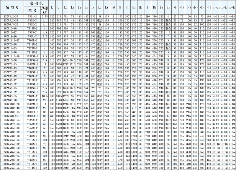
Shape and installation dimensions
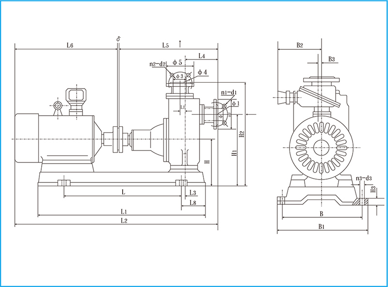
ZX series self-priming centrifugal pump appearance and installation dimension table
- DYB Portable Vane Pump
- HWQB Explosion proof Submersible Pump
- HW Adblue/Methanol Pump Series
- KCB Gear Oil Pump
- KYB Self-Priming Vane Pump Series
- LPG Liquefied Gas Pump
- WCB Portable Gear Pump
- Pipeline Pump Series
- Explosion-Proof Motor Series
- Diaphragm Pump Series
- Flowmeter Series
- Oil Drum Pump Series
- DC Pump Series
- Magnetic Pump Series
- Chemical Pump Series
- Centrifugal Pump Series
- Vacuum Pump Series
- Metering Pump Series
- Rotor Pump Series
- Multistage Pump Series
- Sanitary Pump Series
- Screw Pump Series
- Oil Gun And Small Flow Meter
- Explosion-proof type control cabinet
Scan the code to follow Facebook
Phone/wechat/whatsapp: 15868545868 18968868555
Email: haiwan@haiwanpump.cn
Http: www.haiwanpump.com
Add: Meiao Street, Qiaoxia Town, Yongjia County Wenzhou City, Zhejiang, China

Scan The Code To Contact Us